The Frogbot
Introduction
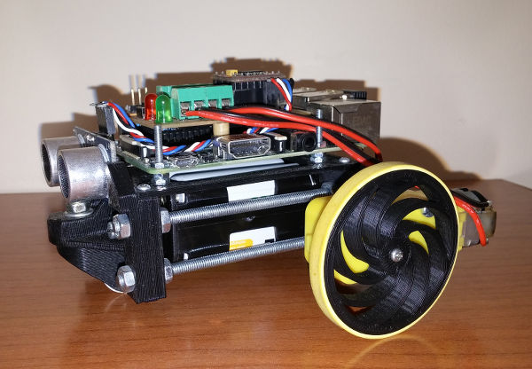
The frogbot is a simple 3D printed robot controlled by Raspberry PI and Brain4it.
It is powered by two low cost DC motors and six AA batteries.
To avoid obstacles, it incorporates an ultrasonic sensor on its front part.
You can program the Frogbot with Brain4it to make it execute a certain routine by its own. If the Raspberry is connected to your wifi network, you can also remotelly control it with your smartphone through a Brain4it dashboard.
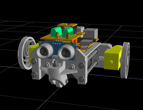
Design
The frogbot was designed to be easy to print. Next you can view the robot in 3D and download its parts in STL format.
Electronics
To make the frogbot you will also need the these components:
- Raspberry Pi B+
- TB6612FNG Sparkfun motor driver
- LM2596 RioRand switch regulator module
- 2 * DC gear motor 3-6V
- HC-SR04 ultrasonic sensor
- 2 * 5mm led
- M4 threaded rod (1 meter)
- 2 * rubber bands
- 20 * M4 nuts
- 2x3 AA battery holder
- 6 * AA batteries
- headers, wires and PCB
The following scheme shows how to connect the components:

Brain4it Code
The Brain4it server for Raspberry Pi has specific functions to read
(gpio-read pin) and write (gpio-write pin value)
the GPIO pins of the device (See the RaspberryPi library documentation
to know more about the operation of these functions).
Each motor of the robot is controlled by 3 GPIO pins: 2 pins control the direction of rotation while the third controls the motor speed by PWM (pulse wide modulation). All these pins are connected to the inputs of the TB6612 motor controller as shown in the circuit.
At start, the Brain4it module initializes the operation mode of all the GPIO pins with the
the function (gpio-mode pin mode), where mode can be:
- in: pin configured to read
- out: pin configured to write
- pwm: pin configured to generate a PWM signal
The function call (gpio-pwmc 8 100) sets the clock divider (8) and the value range (0..100)
for PWM pins. With this setup, the frecuency of the signal will be 24KHz,
high enough to prevent it from being audible.
This is the code that is executed at startup (start variable):
(do
  (### "set pin mode operation")
  (gpio-mode setup/BUTTON "in")
  (gpio-mode setup/RED "out")
  (gpio-mode setup/GREEN "out")
  (gpio-mode setup/LEFT_PWM "pwm")
  (gpio-mode setup/LEFT_1 "out")
  (gpio-mode setup/LEFT_2 "out")
  (gpio-mode setup/RIGHT_PWM "pwm")
  (gpio-mode setup/RIGHT_1 "out")
  (gpio-mode setup/RIGHT_2 "out")
  (gpio-mode setup/STANDBY "out")
  (gpio-mode setup/ECHO "in")
  (gpio-mode setup/TRIGGER "out")
  (### "set default pin values")
  (gpio-write setup/GREEN 1)
  (gpio-write setup/RED 0)
  (gpio-write setup/STANDBY 1)
  (gpio-pwmc 8 100)
)
This module defines the function (motors left right) to set the
speed of the motors. The arguments left and right
represent the motor power (in the range -100..100) of the left and right motors, respectivelly.
The signum of these arguments indicates the direction of rotation.
Calling (motors 50 50) will cause the robot to advance at half power (50%),
while calling (motors 100 -100) will cause the robot to rotate clockwise at full power.
The source code of this function is shown below:
(function (left right)
  (### "left and right in range (-100..100)")
  (### left_motor)
  (gpio-write LEFT_1 (if (> left 0) 1 0))
  (gpio-write LEFT_2 (if (< left 0) 1 0))
  (gpio-pwm LEFT_PWM (abs left))
  (### right_motor)
  (gpio-write RIGHT_1 (if (< right 0) 1 0))
  (gpio-write RIGHT_2 (if (> right 0) 1 0))
  (gpio-pwm RIGHT_PWM (abs right))
)
The distance function mesures the distance (in cm) to the object located in front of the robot.
It generates a high pulse of a duration of 10 microseconds in the TRIGGER pin
of the HC-SR04 sensor to send an ultrasonic signal.
Then the function invokes (gpio-pulse-in ECHO 1 5000000) to measure the time
it takes for the echo of that signal to return to the sensor.
The distance to the obstacle is the result of dividing that time by 100:
(function ()
  (local duration)
  (gpio-write TRIGGER 0)
  (delay 2)
  (gpio-write TRIGGER 1)
  (delay 10)
  (gpio-write TRIGGER 0)
  (set duration (gpio-pulse-in ECHO 1 500000))
  (round (/ duration 100))
)
To remotelly control the robot this module has the following dashboard:
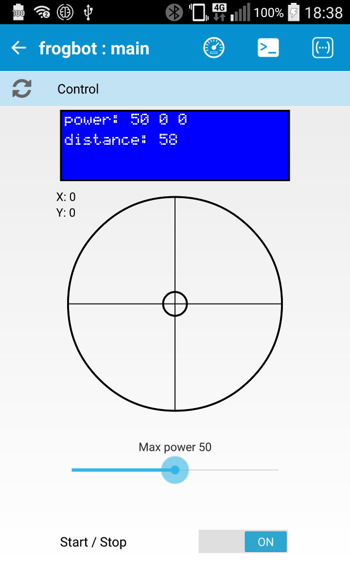
- The stick widget controls the direction and speed of the robot. Moving the stick up or down makes the robot advance forward or backward. Moving the stick left or right makes the robot turn or rotate in that direction.
- The range widget is a speed limiter, that sets the maximum operating power of the motors.
- The display widget shows the power applied to each motor and the distance to the obstacle at real time.
- The switch widget allows you to start and stop the robot main loop.
The stick widget sends to the Brain4it server the coordinates (x, y) of the end of the stick respect the widget center. The function @control converts these coordinates to the left (mot_target/left) and right (mot_target/right) power arguments expected by the motors function:
(function (context data)
  (set-local dx (first data))
  (set-local dy (last data))
  (set-local left
    (round
      (*
        maxpower
        setup/SQRT2
        (- (* setup/COSA dx) (* setup/SINA dy))
      )
    )
  )
  (set-local right
    (round
      (*
        maxpower
        setup/SQRT2
        (+ (* setup/SINA dx) (* setup/COSA dy))
      )
    )
  )
  (### "left and right in [-maxpower..maxpower]")
  (cond
    (when (< left (- maxpower))
      (set left (- maxpower))
    )
    (when (> left maxpower)
      (set left maxpower)
    )
  )
  (cond
    (when (< right (- maxpower))
      (set right (- maxpower))
    )
    (when (> right maxpower)
      (set right maxpower)
    )
  )
  (set mot_target
    (list "left" => left "right" => right)
  )
)
The calculated power (mot_target) is not directly applied to the motors. That task is performed by the main_loop function:
(try
  (do
    (set mot_actual/left 0)
    (set mot_actual/right 0)
    (while running
      (### "take next motor power")
      (set mot_next mot_target)
      (### "calculate distance")
      (set dist (distance))
      (### "check for collision")
      (set collision_risk (check_collision))
      (### "evaluate control rules")
      (eval rules)
      (### "apply next motor power")
      (when (!= mot_next mot_actual)
        (set mot_actual (clone mot_next))
        (motors mot_actual/left mot_actual/right)
        (module-notify "@display")
      )
    )
  )
  (ex)
  (do
    (motors 0 0)
    (set mot_actual/left 0)
    (set mot_actual/right 0)
    (gpio-write setup/RED 0)
  )
)
The main_loop is responsible for giving power to the motors according to the user's request (mot_target), but prevents the robot from colliding against an obstacle.
To achieve this, it measures, in each iteration, the distance to the obstacle that is in front of the robot and activates the collision_risk variable if there is a risk of collision.
When collision_risk is true,
the control rules prevents the robot from advancing even though the user
insists on doing so:
(do
  (when collision_risk
    (if (> mot_next/left 0) (set mot_next/left 0))
    (if (> mot_next/right 0)
      (set mot_next/right 0)
    )
  )
)
See it in action
In this video you can see the frogbot in action.